Servo motor control by PLC programming
Author: Nuttaphong(www.try-plc.com)
1. Basic principle of control.
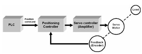
Figure 1 shows the block diagram of the servo motor control system basics. Typically, servo motor control system are key elements in UML.
Motor: Act have both drivers loaded with no brakes and brake
Encoder:attached to the motor to act to move the motor feedback. So we can know the position and speed of rotation from N. Wonder this code.
Servo driver: the current total of the servo controller and Positioning controller together the servo controller will act as a power supply. Positioning controller for the motor to control the position of motion. The motor command from external devices such as PLC.
PLC: a page is to send commands to the servo driver in various forms such as analog and etc. Plus then servo driver controls the motor to rotate the position and velocity as To be ordered.
Servo motor control
From Figure 1, the work will begin with PLC Send Position command, the signal plus or analog to the Position controller in the servo Dive power of the Position controller will add to the Amplifier power to the motor to the motor rotation. to the speed and distance instruction code N. Der affixed to the motor acts feedback and information from. Early in the rotation back to the Position controller that it should have Counter function compared to orders received from the PLC if it is different, it signals to the Amplifier to add to the motor rotation to the distance and speed as needed.
2. Structure of the servo motors.
Omron Servo Motor Type AC Servo Motor is a Synchronous ServoMotor structure looks as follows.
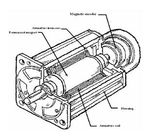
As part of a stator coil slot of thousands in the groove is a permanent magnet rotor. Therefore, the relationship of the parameters will be similar to this type of DC motor and motor brush maybe not so called. DC Brushless Servo Motor as a private code N. Wonder is connected to the same rotor shaft.
3 Principles of the Encoder
Encoder that used to servo motors There are two types as follows.
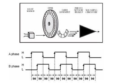
Encoder An Incremental. Figure below shows the components of N. This type of code Der. The beam is shot through the lighting diode fixed disc to the rotation disc is installed on the shaft axis, with a photo diode sensor. Beam going through holes on the fixed disc and the rotation disc by timing the rotation makes the electrical signal from photo sensor, as the pores of the A and B on the fixed disc is different phases together is 90 degrees, so signal output of electricity will wave at out each phase is different by 90 degrees on the Z form of the hole fixed disc, only one hole only.
If after the Power Company from encoders Wonder is the angle of rotation itself the output phase A and B at different phases together is 90 degrees is pointing to the direction of rotation of the motor of phase Z or Zero signal is a pointer to the 0 degrees of rotation.
Encoder interfaces Absolute In general, absolute encoder is output as a code to gray code, binary or BCD code, but for the type of detector of the servo. No need to select the output code. Just select the desired resolution, but use only Will notice that something is different from the incremental encoder is the number of cable output is more than an incremental, which depends on the resolution selected. And another is. The meaning of the absolute encoder signal at a time will come for the full value. They are not comparable from the beginning as an incremental encoder, so if the servo motor with an absolute encoder detector did not have to search for starting position (origin search) new every time. Turn off and then turn up for a new job.
4.Types of input controls for servo River Dive.
Dive servo input power. The more active the PLC There are several but the most popular was the Pulse Train and Linear (or Analog) is the second model is appropriate to work differently for Pulse train is suitable for job position control, such as Feed. -to-Cut and Pick & Place as an example of Linear motion is applied to work as a curve or circle. Here we will focus on the servo power Dive receiving an input signal Pulse train to make it easier to understand for beginners.
4.1 PULSE TRAIN CONTROL.
PLC sends a signal to the servo Plus Dive Dive Power then Power. To control the rotation of the motor to be under the command of the PLC from the movement or rotation of the servo motor is based on the number of Plus PLC sent the same speed of the servo motor depends on the speed or frequency of Plus, from the PLC as shown
4.2 PULSE WIDTH MODULATION (PWM)
The work is similar to the range of Pulse Train rotation depends on the number of Plus. But the speed of the motor depends on the width of the Plus.
4.3 LINEAR.
This control is different from both As mentioned above, because PLC analog signals to the servo power Dive. The Dive is a kind of power will be able to control the analog signals as well
5 Control system of servo motors.
Under the above is. Describes broad principles. The servo motor. Here we will practice that can be actually implemented. But the main focus, such as PLC control and servo power Dive will not mention as mechanical systems, such as Ball screw, belt, including mechanical calculations, such as Torque.
|